GUI Application for the Object Oriented Simulation Tool for FMS
USER MANUAL
The GUI Application for the FMS-OOST is coded in Visual Basic 6.0. This application is an executable file created from the final program. The other components include an MS Access database (FMS.mdb), a clear executable, a plant executable and a supervisor.cpp C++ program that is called by the plant program.
Follow the following steps to run the application once all the installation steps are accomplished.
1) Starting the Application
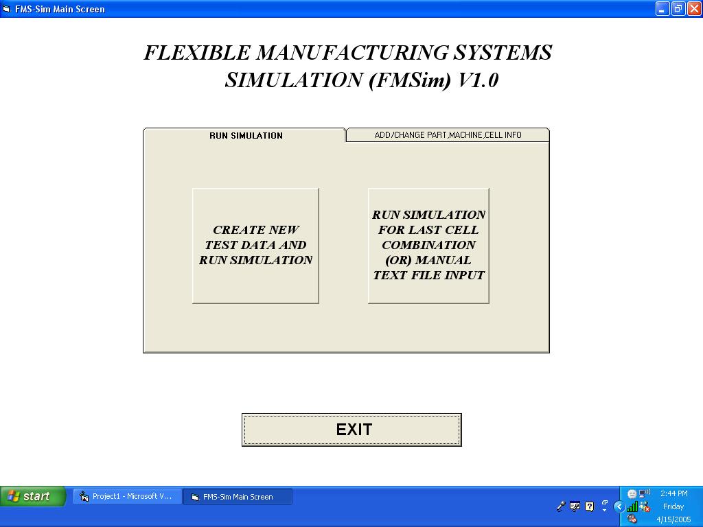
Double click FMS-Simulation.exe to start the application. The main screen that appears is shown in Figure 1 below:
FIGURE 1: MAIN SCREEN
2) Running the Simulation
Select the RUN SIMULATION tab (this is usually selected be default) as shown in Figure 1. There are two options that a user may choose to run the simulation. Each is discussed in detail below.
i) CREATE NEW DATA AND RUN SIMULATION
This option as the label indicates allows a user to create new test data for the simulation. If this option is desired the button is clicked and a new window (Cell/Part-Type Selection) is opened as shown in Figure 2.
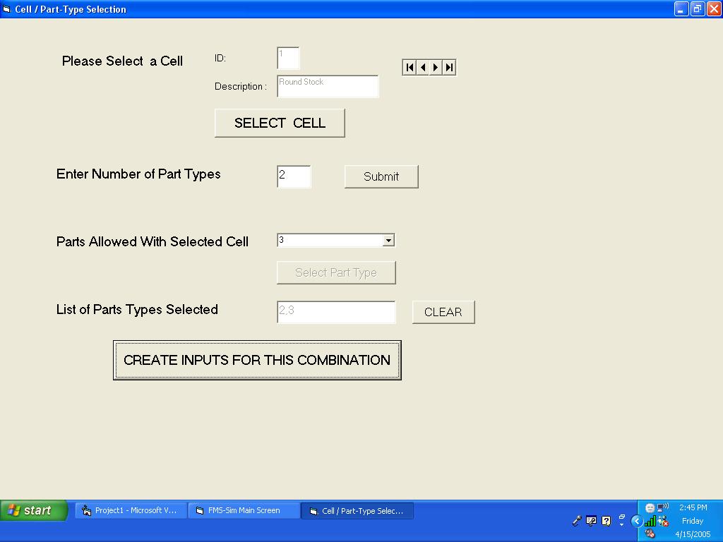
FIGURE 2: CELL / PART-TYPE SELECTION WINDOW
a) In this window, to select the cell desired, choose a cell by clicking the left/right arrows till the desired cell number and name appears in the text boxes.
b) When the desired cell is found, click the SELECT CELL button to confirm selection.
c) In the next step, the number of part types is entered and click Submit. To find out how many and what part-types are possible, the Parts Allowed With Selected Cell combo-box may be viewed.
d) To select the desired parts, choose the part from the combo box and click Select Part Type. The List of Part Selected textbox shows the selection.
e) Once all the the selections are made, click CREATE INPUTS FOR THIS COMBINATION.
f) A new window Run Simulation appears and this window is shown in Figure 3.
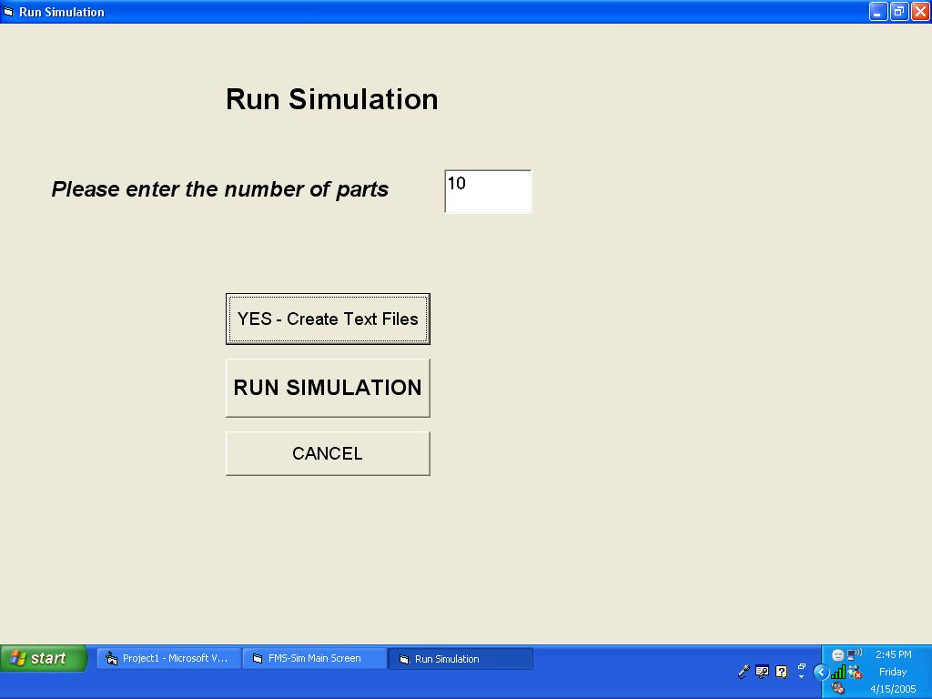
FIGURE 3: RUN SIMULATION WINDOW
g) Once the desired number of parts are entered in corresponding text box, the CREATE TEXT FILES button is clicked.
h) Finally, the RUN SIMULATION button is clicked. The corresponding output files can be found in the files folder.
ii) RUN SIMULATION FOR LAST CELL / MANUAL TEXT INPUT
This simulation application also allows the user to either, re-run the simulation for the last cell input run whose text files already exist, or run the simulation manually for user defined text files. In either case, the simulation takes you the Run Simulation window, and the steps from Step: f ) through h) shown in the section above are followed. If user defined text files are used, the text files are placed in the c:\files\ folder.
3) Add/Change Part, Machine and/or Cell Information
If a user would like to add new parts and machines, build new cells, or edit existing information, the ADD/CHANGE PART, MACHINE, CELL INFO tab is selected from the main screen shown in Figure 1. The tab that will appear is shown in Figure 4. As the buttons indicate, depending on the component that needs to be created or needs editing, the corresponding button is clicked.
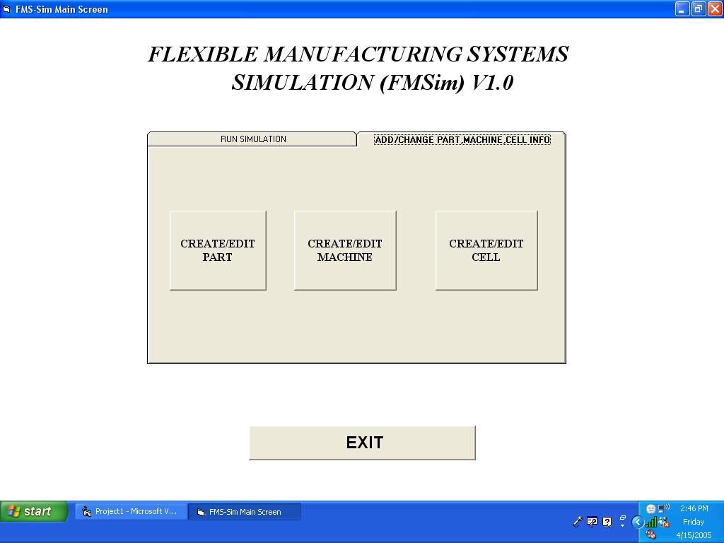
FIGURE 4: CREATE/EDIT CELL, PART OR MACHINE WINDOW
Copyright Bharath Natarajan 2005